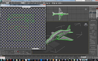
Once I was happy with the model it was time to apply a material too it. I decided that the best way to do this was to use a term know as UVW mapping. I had never used this method beforeso was keen to learn a new skill.
In the modifier panel I clicked on Unwrap UVW, scrolling down to Edit UVW I then clicked to flatten the map. This allowed each piece to be clearly identified in the box. Choosing Select elements allowed me to individually move the pieces of model around. I chose the ones that needed colour on them and layed them out in the box so it looked like the original model. I had to ensure that all the pieces were kept inside the box. Then clicking on render I changed the height and width to 2048 so it is big enough. I then saved the file as a PNG.
I then opened Adobe Photoshop and created a new layer. Referring to the images I have collected of the red arrow aircraft I carefully copied the colour scheme so it looked exactly the same. Everytime I created a different section I used a new layer and found by 'locking' two layers I didnt edit them all. Once I was happy with the design I saved the image as a JPEG and went back into 3D Max.

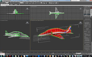

I noticed from the front of the aircraft that the white strip did not meet up and the back wing did the same. So I unwrapped the UVW Map again and selected the sections of the model I had missed. I then rendered the map and they were now included.
No comments:
Post a Comment